Measuring Tips
General Information
The ordering of cables and lines from this site is relatively simple and intuitive.
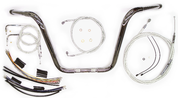
You can either search for product information on this website knowing the application of the product by providing the make, model, and year of the motorcycle in our "Search by Bike" fields or, you can custom design a control cable or brake/hydraulic line by using the custom order forms displayed for each product category.
Or, if you prefer, you can call us anytime M-F between the hours of 8:30 AM and 5:00 PM EST for our personalized expert assistance. Our Customer Service Tel. No. is (585) 381-8380, Ext 3.
To see a measuring print or image for each separate product that you’re interested in, you can view it on the specific product page. Or, you can go into Custom Size Ordering and select a Custom Guide to see what our measuring requirements are for each product.
We do not make specific recommendations as to the “ideal length” you may require when making handlebar changes or simply wanting to upgrade your cables and lines. This depends on your personal routing preference. However, that information may be gathered from the following suggestions:
1. Contact the manufacturer of your aftermarket handlebars to inquire into what they recommend for the year and model of your bike.
2. Check on-line with the HD Forums to see if there is a rider that has made the same changes to their bike to see what extended lengths they used.
3. DIY, … using your existing bars, or, by holding and comparing your new handlebars against your current bars, use your preferred routing to measure the distance from connection point to connection point. Note: If your existing cables and lines are stock lengths, you can determine your new length by using our “Search by Bike” Application. By providing the make, model, and year of your motorcycle, your stock control cables and brake lines will be displayed along with alternate length options. If your existing cables and lines are not stock, or you are not sure, you may need to measure the lengths of your existing cables and lines using a tape measure.
4. DIY … from scratch using your own routing preferences and taking your own measurements. Care must be taken to use a cable or line substitute that will bend, flex, and route similarly to an actual control cable or brake line. Common household or shop items to accomplish this might include a length of small diameter plastic or PVC tubing, CATV coax cable, perhaps a ¼” rubber hose, or even ROMEX 14/3 or 12/3 vinyl jacketed electrical wire to accurately simulate your best routing path and length.
If you do choose to order a custom cable or brake line, you will need to determine all the measurement information required in our custom order forms for us to process and accurately manufacture it.
Throttle / Idle / Idle-Cruise Cables
(These three different control cables are treated basically the same)
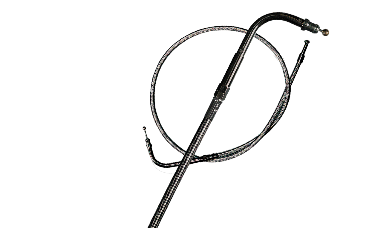
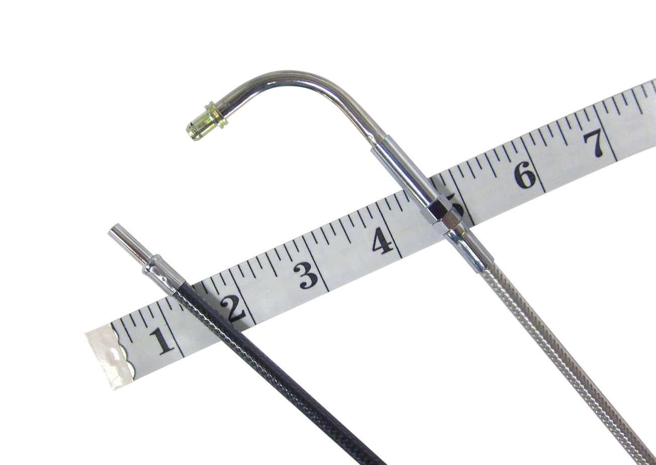
1. You must first determine the bend angle of the bent tube adjuster assembly at the handlebar end of the cable. Different handlebar designs require different routings for personal aesthetics andsafety. You have three different angles to choose from. 45°, 70°, and 90°
2. When planning your routing, be sure to watch for any potential interference, the choice of the bent tube angle may look good, but will it hit the fuel tank or other parts? Also try to pick a routing option that keeps the cable clear from paint or chrome and avoids sharp bends.
3. If you are upgrading your stock cables but not changing your handlebars, simply look up your bike on our Search by Bike fitment guide to choose your optimal length from the plus/minus and stock lengths.
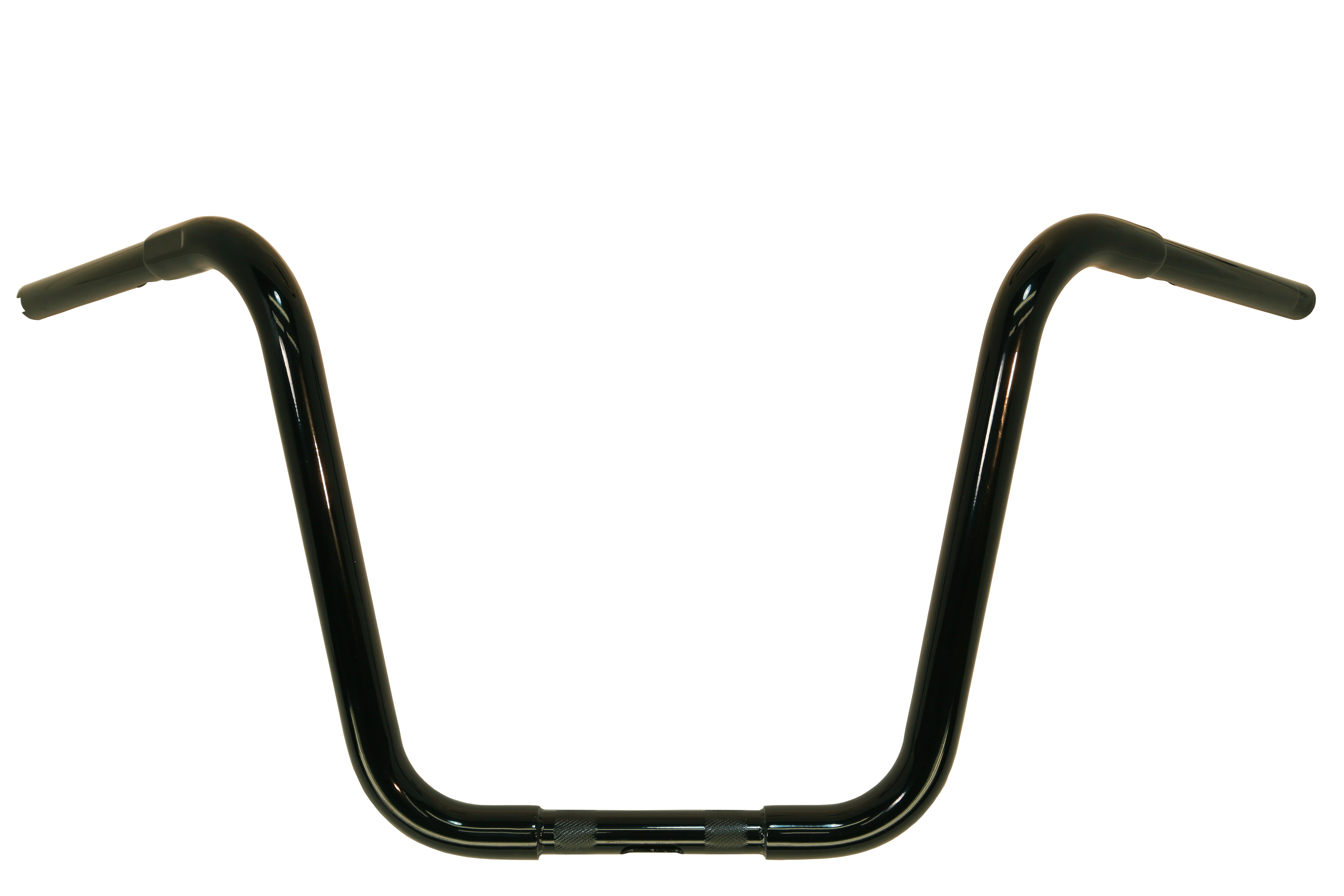
4. If you are changing your handlebars, you might want to hold and compare the new handlebars against your current bars for reference. You can then use your stock cable as a template and measure the difference, whether longer or shorter, to determine your new length
5. Alternatively, if your cable is not stock, or is not a direct stock replacement Harley-Davidson P&A cable, then you must measure from connection point to connection point. For example, a length of small diameter plastic or PVC tubing, rubber hose, CATV coax cable, or a length of ROMEX jacketed electrical wire to create and measure a routing path from scratch.
6. Once you have found a good path for the cable given your chosen bent tube adjuster angle, use the product diagram guide images on any of the throttle or idle pages to find the length of that bent tube. Then, take the total length of the cable and subtract the length of the bent tube – this will be your housing length .
7. When using our Custom Ordering Guide images, please make sure your information is properly filled out in all of the required fields on the order form so we may accurately and correctly process your custom order.
Clutch Cables
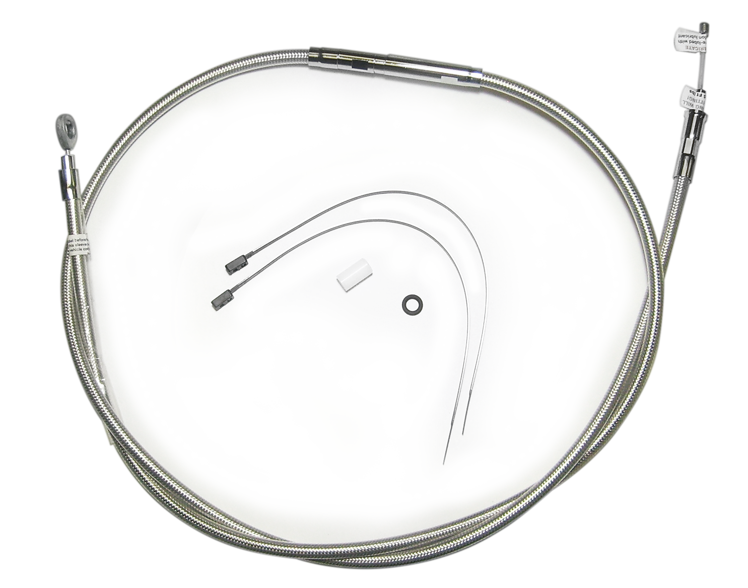
Usually when designing a clutch cable, the lower leg cable length doesn’t typically change because this ensures the correct factory intended location of the adjuster. Keeping this in mind, when making a handlebar change, you are typically only changing the length of the upper leg of the cable which will result in a new total length.
1. When measuring a clutch cable for replacement, it is very important to consider the adjuster location to make sure it is easily accessible when it is necessary to maintain the clutch adjustment. You will also want to keep it above the transmission oil level that pools inside the lower leg. It is usually located from the factory mid-way on the frame down tubes. We recommend you try to position the adjuster close to this stock placement.
2. To determine your stock lower leg length, upper leg length, and total cable length, look up your bike on our Search by Bike fitment guide.
3. If you are upgrading your current stock cable but not changing your handlebars and need to determine a cable length requirement, use your stock cable for a template and measure the difference to the current handlebar controls, whether longer or shorter, to determine your new upper length and TOTAL length. Then look up your bike on our Search by Bike fitment guide in order to choose your optimal length, i.e., the plus/minus and stock lengths listed.
4. Alternatively, if you are changing your handlebars, you might hold and compare your new handlebars against your current bars. Use your stock cable for a template and measure the difference from the cable to the desired handlebar controls location, whether longer or shorter, in order to determine your new upper length and new TOTAL length.
5. If your cable is not stock, or is not a stock direct replacement Harley-Davidson P&A cable, then you must measure from connection point to connection point to determine the length needed. A suggestion might be to measure with a length of small diameter plastic or PVC tubing, rubber hose, or CATV coax cable.
6. When planning your routing, watch for tight bends and rubbing of painted parts and try to keep the cable away from sharp edges such as the triple trees.
7. When using the Custom Ordering Guide images, make sure your information is properly filled out in all of the required fields on the order form it insure that we can accurately and correctly process your custom order.
Brake Lines
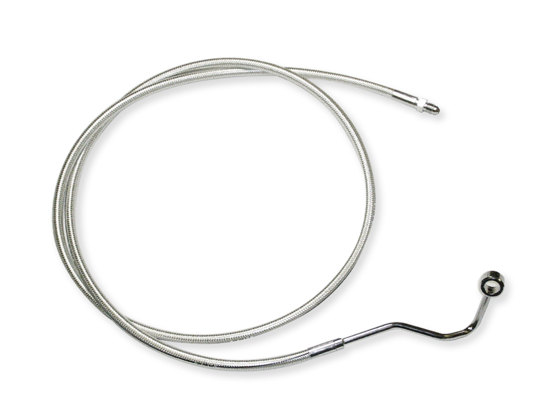
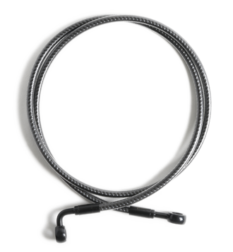
1. All types of brake lines are measured similarly and are shown on the various diagrams in the brake line product pages. See (Custom Size Ordering / Brake Line Guides) and click on the model descriptions to display the Diagram Guides for your brake line type.
2. First, determine the bend angle of the master cylinder banjo. The fitting at the handlebar should route the brake line in a safe and visually acceptable direction. Different handlebar designs and master cylinder orientations require different routing for personal aesthetics and safety. You have several angles to choose from: 180°, 35°, 60°, and 90°
3. If you are going to alter the routing of your brake line, avoid a path that may hit the fuel tank or other parts. Also try to pick a routing option that keeps the line clear from paint or chrome and avoids sharp bends. Note: The line should have touch points where it can be securely and safely mounted to without creating a tug or pull on the brake line when steering or compressing the bike’s suspension. Make sure to leave enough length to accommodate movement of the front forks or the rear swing arm.
4. If you are upgrading your brake lines (but not changing your handlebars) and have determined your optimal routing preference would require a length change, you can use your stock brake line as a template and measure the difference, whether longer or shorter, from your current master cylinder location to determine your new length. Then, look up your bike on our Search by Bike fitment guide to choose your preferred length from the listed plus/minus and stock lengths.
5. Alternatively, if you are changing your handlebars, you might hold and compare your new handlebars against your current bars. Then, use your existing brake line as a template and measure the difference from the desired master cylinder location, whether long or short, to determine your new upper length and TOTAL length.
6. To measure your brake line routing from scratch, use an aid to duplicate the flexibility of a brake line hose when determining your routing. A suggestion might be to measure with a length of small diameter plastic or PVC tubing, rubber hose, or CATV coax cable. Be sure to follow the routing tips mentioned in the above item No. 3.
General Reference - Brake Line Measuring Information
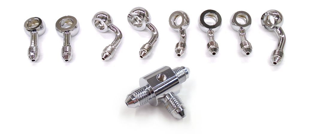
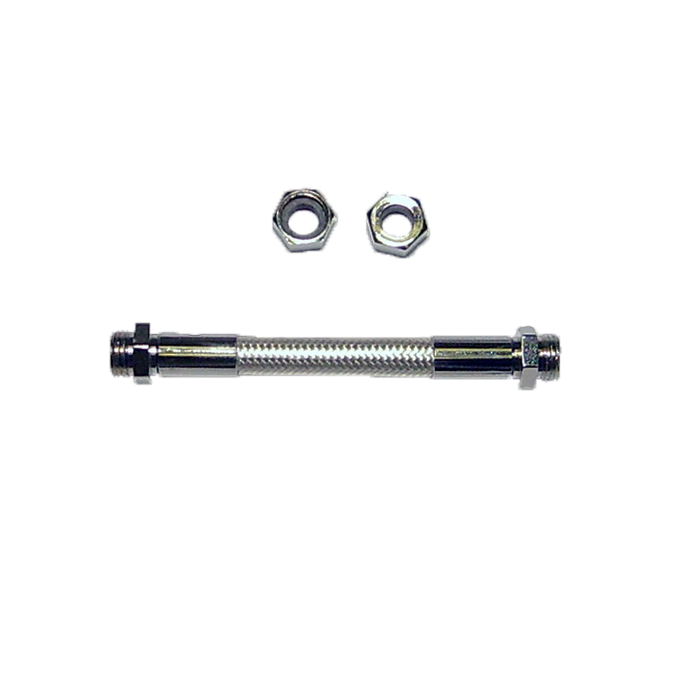
1. Universal (AN3 type thread-together) lines are not measured to the edge of the nut, but rather inside the nut at the face of the flange where the actual sealing connection is made. Make sure you leave room for the adapter or banjo fitting you will be using, they can add 2 or more inches to the length of a universal style brake line.
2. Custom Single Disc Brake Lines are measured from specific designated locations on the banjo fittings (banjo face or banjo hole centerline) per the Custom Ordering Guide diagram on the Product Page.
3. Upper Designer Kits are measured from the top of the lower triple tree to the master cylinder.
4. All brake line assembly types have dedicated diagrams on the product pages found under (Custom Size Ordering / Brake Line Guides) that show how the banjos and brake lines are measured.
5. Rear kits and Lower Designer Kits usually do not require changing – If you have special requirements for anything other than a stock kit, call or e-mail us regarding ordering these with custom specifications.
6. When using Custom Ordering Guide images, make sure your information is properly filled out in all the required fields on the order form in order so we may accurately and correctly process your custom order.
Ignition Wires
1. Ignition wires use similar measuring steps as cables and brake lines.
2. They are measured terminal tip to terminal tip per the measuring diagram. Refer to: (Custom Size Ordering, Ignition Wire Guide, Custom Length Ignition Wire Diagram.
3. Your terminal ends need to match the particular coil you are using.
4. If possible, make sure the ignition wires do not touch or rub each other, hot engine components, or sharp edges like a bracket.
5. The ignition wires are coated with a heavy walled FEP dielectric coating. Care must be taken to insure against anything cutting into this clear coating. This may create a static “capacitor leak” and can cause electrical interference and possible running issues.
